|
|
|
|
|
|
Mounting notes for magnetic switches
If the switch is mounted on ferromagnetic material, the switch distance will be reduced. By mounting a cross-polarised permanent magnet on ferromagnetic material, the field of one of the poles increases and so the whole field increases. Thus the available switching distance becomes larger.
If a longitudinal-polarised permanent magnet is mounted on ferromagnetic material, a part of the magnetic field will be short-circuited and thus attenuated. The available switching distance becomes less.
Recommendations for the protection of reed contacts against overload
Reed contacts are sensitive to high current loads. The spring resistance of the contact studs is relatively low. Already a short-time overload produces a welding effect between the studs. The result is an increase of the transition resistance or a sticking of the contacts. Because of the extremly fast switching of the reed contact, high self-induction voltages could occur through the switching off of inductive resistance such as relays, lifting magnets, electrovales etc.
Measures to save contacts
 |
Inductive load:
For constant voltage, a recovery diode is switched in parallel to the load in off-state direction. Thus the reverse selfinduction voltage will be short-circuited when opening the contact.
|
 |
For alternating voltage a RC-module is switched in parallel to the contact in order to remove sparking.
Dimensions of the RC-module:
Ri in Ω ~ R in Ω of the load
C in µF ~ I in ampere
|
 |
Capacitive load:
For constant or alternating voltage a resistance will be connected in series to the capacitive load. Thus too high switch-on currents can be reduced.
|
 |
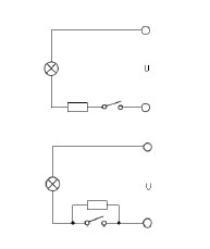
Load on the lamps:
Tungsten filament lamps have, if cold, a ten times lower resistance than if hot.This means that during switch-on, for a brief time, a ten times stronger current flows then if hot. A resistance connected in series can reduce this current up to an allowable limit value. Alternatively, a resistance in parallel to the reed contact can preheat the filament up to just below the glowing state. Both methods result in higher loss of power.
An optimal protection circuit has to be evaluated for every situation. A badly designed protection circuit can be more infavorable than none.
|
Back
|
|
|
|
|


