|
|
Products
Security switches
switches for security-relevant switching functions
|
|
| Your personal contact person |
Phone: +49 (0) 7522 / 68 98
Fax: +49 (0) 7522 / 93 08 252
Engineering
Andreas Fritzenschaft
Walter Hoffmann
Sales
Ingo Kamp
Purchasing
Anneliese Bauer
|
|
|
Schematics
|
Type
|
Switching
distance,magnet
|
Contact mode
and element |
Electrical specifications
|
Connection
|
Order-No.
|


|
|
|
 |
R
| |
|
|
|
Actuation

| |
|
Schematics
|
Type
|
Switching
distance,magnet
|
Contact mode
and element
|
Electrical specifications
|
Connection
|
Order-No.
|


|
|
|
|
|
|
|
The actuation magnet SM 5 PZ and the evaluation model SB-UEG9-PZ belong to the proximity switch for security functions KMS
5 PZ. All components comply EN 954-1: 1996 Kat.2 / EN 55011: 1998 requirements and are entitled to bear the mark of
conformity. The security switch KMS 5 PZ can only be actuated with the encoded magnet SM 5 PZ. When the magnet approaches
to the security switch correctly from the top (markings switch/magnet must correspond), the individual magnetic fields will be
recognized correctly at a distance not smaller than San and the switch will be released. When moving the magnet away and
upwards, the security switch reverts to a secured state beyond distance Sab. The security switch is error redundant, i.e. the
occurence of up to two errors at the same time (cable breaks, etc.) results in a secure switch off. Switch, magnet and evaluation
module are not paired and thus there is no fixed correspondence between the individual components. If the actuating magnet
approaches to the switch by more than 2 mm closer than distance San, the security switch will switch off.

Mounting/actuation:
Take care that switch and magnet lie accurately one on top of the other. Markings (labels) have to be on the same side.
The position of the mounting can be as you like.
Fixing:
Fasten with 2 pcs. screws M3 as well as split washers according to DIN 127 or spring washers according to DIN 137
or counternuts according to DIN 7967.
|
| |
|
|
|
|
|
|
| |
|
Schematics
|
Type
|
|
|
|
|
|
Order-No.
|


|
|
|
|
|
|
|
|
|
Visual indication: Switching status K1 and K2
Output: 1 make contact, 1 fault message, potential free
Power approx.: 2 VA
Switching voltage: max. 220 VAC
Switching current: max. 10 A
Switching power: max. 1500 VA; 24 VDC/200 W, 48 VDC/50 W, 250 VDC/80 W
The unit SB-UEG5-24-R controls the switching behaviour of 1 to 5 combinations NO/NC. The evaluation is made by
two relays, K1 and K2. When actuating the transmitters correctly (NO closed, NC open, green LED on, red LED off)
a contact NO between clamps 25 and 27 is available for the user. If the contact NC is not correctly actuated, K2 picks
up (red LED on). In this case the clamps 26 and 27 could be used as fault detectors. There is also a possibility,
through the clamps 20-24, to visually display the switching status of the NC of every NC/NO combination via the LED’s.
| |
|
Schematics
|
Type
|
|
|
|
|
|
Order-No.
|


|
|
|
|
|
|
|
|
Supply voltage (protection against polarity reversal): 24 VDC
Supply current: 0,1 A
Notification output (not short circuit proof): approx. 22 V, max. 15 mA
Switch output: 2 NO potential free
Switching voltage: max. 230 V AC/DC
Load current: max. 4 A DC, 2 A AC (cos φ = 0,3)
Switching power: max. 150 W/1500 VA (cos φ = 1)
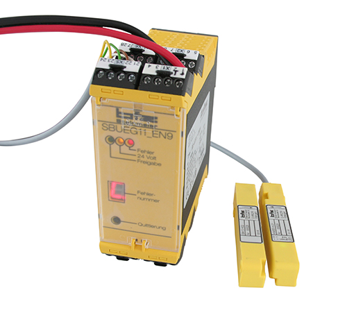
The interpretation component SB-UEG9-PZ meets all requirements according to EN 954-1: 1996 Kat.2 / EN 55011: 1998.
The component evaluates the signals of the connected security switch KMS 5 PZ and offers two electrically isolated contact
switches (7/10 and 9/12). The enabling signal is indicated by the LED. On release approx. 22V / 15mA are present at
clamp 8. The control module is error redundant, i.e. the occurence of two errors at the same time leads to security switch
off. Transmitter and evaluation module have not being paired, there is no fixed correspondence between the individual
components.
| |
|
Schematics
| Type
|
|
|
|
|
| Order-No.
| 
| | | | | | | | Control unit for magnetic switch KMS5-H01 / Article: V00GK000007
Security category 3
Performance level D
according to DIN EN ISO 13849
Cable length 8 m Security magnetic switch KMS5-H01 / Article: V00KM000215 Magnetic system for security switch SM5-H02 / Article: V00MG000024 Magnetic security technology for controlling 1 up to 4 touchless sensors by an individually wired evaluation unit. Typical applications are monitoring protection units on machines and plants. Covers which have been taken off or not properly closed are detected immediately and dangerous machine motions can be prevented. The switching distance of 4 mm or 9 mm allows the hidden mounting of the sensors and actuation magnets. Magnetic switches are almost completely non-sensitive to environmental influences or soiling of any kind, compared to mechanic switches. Special features:
- Status LEDs for quick adjustment of switching distances
- Plug & play technology allows the evaluation unit to detect 1 to 4 sensors
- Display of error diagnosis on the evaluation unit
- Flexible integration of the system, also in existing plants/machines
- Choice between manual or automatic start-up mode
- Two potential-free switching outputs for direct switching of loads up to 250V/4A
- Reporting output for every sensor
- Output for collective reports
- Classification PL of category 3 according to DIN EN ISO 13849-1:2008 and DIN EN ISO 13849-2:2013
- EC-type examination certificate by DEKRA EXAM GmbH | |
|
|
|
|


